Current flowing through the coil of therelay creates a magnetic field which attracts a lever and changes the switch contacts.

To know more about how to use a relay , you might consider to visit this website :
- How to use a relay
Pin configuration of a physical relay :


How to choose a suitable relay ? You can read more about it HERE !
In this post, I will talk about the making of a single channel relay module using a SPDT 12VDC relay.

First of all, I design the schematic in Eagle Cadsoft Professional Version 6.2 . Below is the schematic that was designed by me.Relay required 3 connections which is VCC, GND and output from MCU to trigger it.

Next, I proceed to design the layout of this module board.

Then, when everything is done, it is time for hardware construction process.I start off by making a DIY PCB board for the relay module. I will talk more about DIY PCB on another blog post.


Finally when the relay module is done, I connect it to my arduino UNO. I connect the relay to pin 8 of my arduino. Well, I connected a 9V battery to the VCC and GND to GND of the entire circuit. Most of you will be wondering why am I using a 9V battery instead of taking 5V directly from my arduino ? Well, the answer is that I am using a 12V DC relay . A 5V is not able to supply enough current to 'ON' my relay. On the other side, I connected as in below :

So when the relay is ON, the COM pin will switch and connect to the NO pin which then complete a simple circuit as shown.
I am using a serial bluetooth module to control my relay module wirelessly. I will highlight about this serial bluetooth module in the other post.

Ok! Done with setting up. Now, I upload the below sketch to my arduino UNO. If you have connected the 'Rx' and 'Tx' pins of the bluetooth module to your arduino, please disconnect them while you upload the sketch into your arduino to avoid interfere.
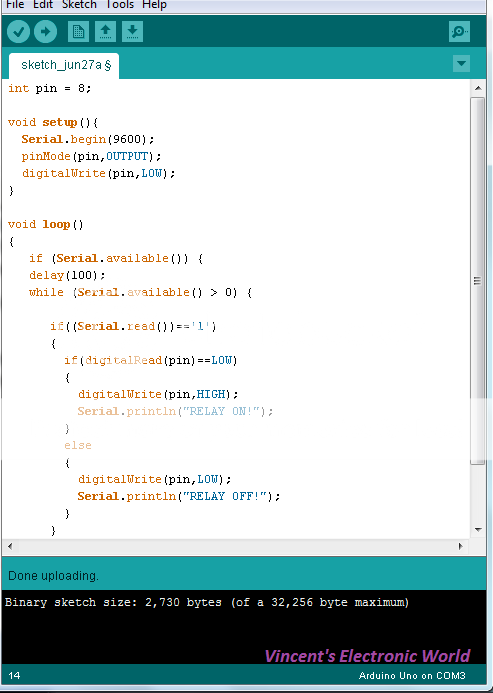
Download Code:
I programmed my arduino to turn on the relay when I press/type '1' in my keyboard or my mobile android phone.
A simple demo video:
Thanks for reading and hope you enjoy !
-VK
.jpg)
Google+
Nice project..
ReplyDeletewww.daxtronics.com.my for student price electronic component..
Thanks !
DeleteOkay, I will edit my post by adding in how to connect a relay !
ReplyDeleteThanks